Programmable logic controllers are at the heart of industrial automation where they enable the precise control and regulation of machines and processes. They offer flexibility, reliability, and efficiency in numerous applications. You can find detailed information and answers to frequently asked questions in our FAQ section.
Electrical and mechanical systems are automated in almost every process technology plant. The automatic control of components based on switch positions or after a certain time has elapsed are examples of this. Sometimes only simple binary links are required; however, complex sequence controls are often necessary. Programmable logic controllers (PLCs) are typically used for automation.
A programmable logic controller / PLC can be thought of as a small computer that performs outputs based on inputs and operations. A PLC consists of at least a central processing unit (CPU) and input/output modules (I/O modules). The I/O modules are usually connected to the central processing unit via a system bus, which also supplies them with voltage.
")
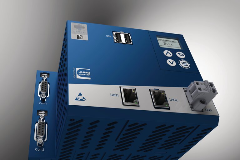
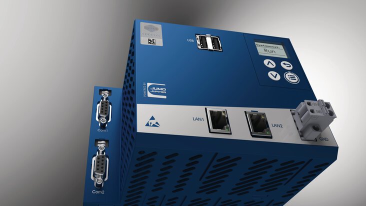
JUMO variTRON 500 central processing unit with PLC functionality, input/output modules, and web panel (behind)
PLCs are available in various versions, which differ in terms of functionality and application:
These controllers are integrated in a single housing. They contain all necessary components such as CPU, inputs/outputs, and communication interfaces. They are ideal for smaller applications with minimal space requirements.
These systems consist of a central CPU and separate input/output modules that can be added or removed as required. They offer flexibility and expandability for more complex applications. This also includes the automation systems of the JUMO variTRON family, even when they have a much wider functional range than standard PLCs.
These controllers have been especially developed for safety-critical applications and meet strict safety standards. They are used in areas where the protection of people and plants is a top priority.
The signals from switches, sensors, etc. are forwarded to the central processing unit via input modules so that they are then available in the PLC. Examples of signals from the plant include the respective status of limit switches, thermostats, flow monitors, and level switches as well as the corresponding measured values from temperature, pressure, or humidity sensors. The PLC links the signals and produces a result, which is made available to the output modules. For example, relays are used to activate solenoid valves and engines. Consequently, the functionality of a PLC is implemented in the central processing unit, which acts as the control center in a manner of speaking.
Before the introduction of PLCs, control systems were implemented by interconnecting relays and time relays. Such control required a significant amount of material, and the function could only be modified by changing the circuitry. In addition, the systems were prone to malfunction and troubleshooting was time-consuming. The task of the first PLCs was to replace these relay networks.
All input signals are processed cyclically by a PLC program and linked in the program. Development environments such as CODESYS are available for PLC programming, which means that programs are developed in CODESYS and then transmitted to the PLC.
A PLC can be programmed in various programming languages defined in the IEC 61131-3 standard. The programmer is therefore able to choose the programming language that is best suited to the respective requirements.
The ladder logic programming language, which has been in use since the 1960s, is suitable for replacing relay networks. It is the oldest known programming language. Its program representation is similar to that of electrical circuits.
Imagine a very simple application in which an input module acquires the status of a limit value switch in a tank and that of 2 push-buttons. The respective statuses are available in the PLC program via variables with the names “LevelBelowTheLimit”, “PushbuttonLeft”, and “PushbuttonRight”. A pump is controlled via the relay of an output module. It is addressed in the program by the name “PumpActivated”). The pump should only be activated when both push-buttons (both − for safety reasons) are pressed and the point level has been dropped below. The simple program in the ladder logic programming language appears as follows in CODESYS:

Example program in ladder logic
You can see a similar structure to that of a circuit diagram, consisting of switches/push-buttons and relays. Once the program has been created, it is transferred to the PLC and verified. After that, the CODESYS development environment is no longer necessary.
Very early on, timing elements were available in ladder logic programming language that enable delayed switching on/off or activate their output for a certain period of time after being triggered. For example, a function block with the designation TON is available. It only activates its output signal when its input is activated for a minimum duration. If, for example, the pump is to be activated when the push-buttons are pressed for a minimum of 5 seconds, the small program must be modified as follows:

Modified example program in ladder logic
The standard function modules also include RS flip-flops, counters, timing elements (such as switch-on and switch-off delays), and edge detectors. Mathematical operators are also part of the standard programming equipment.
Another very similar language is the network-oriented function block diagram. In this language, the small program is structured as follows:

Example program in function block diagram
CFC (continuous function chart) is a further development of function block diagram which allows elements to be positioned freely. Otherwise, CFC is very similar in appearance. The programming language is very common. In it, the program looks as follows:

Example program in continuous function chart
A language that is relatively rarely used today is instruction list (IL), which is very similar to the programming language assembler. Each instruction in IL is primarily based on loading values into an accumulator, which occurs through the LD instruction. The respective operation is then performed with the first parameter from the accumulator. The result of this operation is returned to the accumulator. The small program is structured as follows in instruction list:

Example program in instruction list
Another programming language is ST code (structured text). ST code is a text-based programming language that enables complex control tasks to be performed. Its syntax is similar to that of the Pascal programming language. It allows the use of variables, functions, loops, and conditional statements. ST code is particularly well suited for programming complex process sequences and mathematical calculations. It enables structured and clear programming, which makes the maintenance and further development of control programs easier. Only 2 lines are required for the sample program in ST code:

Example program in structured text
The sequential function chart language is ideal for implementing sequence sequence controls. Imagine a thermal treatment plant in which the material to be treated is conveyed into the plant via a belt conveyor. The first 3 steps are as follows
In programs written in sequential function chart, certain steps (e.g. heating and loading) are linked to one another by switch conditions or transitions. The first 3 steps (+ BasicPosition) of the program required for the example application appear as follows in the sequential function chart language:

Linking of process steps in sequential function chart
Programs can be defined for each step, but they are only carried out when the corresponding step is active. Processing begins with the “BasicPosition” step. No program is stored for this step, so no activity takes place.
Separate programs (e.g. in ladder diagram) are defined for all further steps. If the start push-button is pressed from the BasicPosition, the “Heater” step is activated so that the heat generator is enabled by the stored program. The step remains active until the heater temperature reaches 200 °C and the “Retract” step becomes active. The program in the “Retract” step enables the corresponding control for the door and belt engine.
Accordingly, further steps are added with transitions. The last transition activates the “BasicPosition” step again.
One of the core functions of a PLC is the automation of processes, which requires programming in one of the programming languages mentioned above. However, today's PLCs are automation all-rounders and offer much more: